Relay Switching
This article is about a two-channel relay switching device that turns OFF power to the second channel when power to the first channel is applied. This is useful for preventing power failure or blowing fuses due to high currents. The second channel could be a heater or electric oven that can be temporarily turned OFF. The first channel is could be an electric kettle that is ON for a short period of time and thus disables the power of the second channel temporarily (a few minutes) to reduce the amount of total current leaving the power supply.
The circuit has no load short circuit protection.
Step 1: Design the Circuit
The circuit was designed and drawn via PSpice simulation software:
The Rcurrent resistor is used to measure the current and thus turn ON the relay. The relay turns ON when the Rl1 current exceeds a certain value.
Calculate the maximum input current:
Imax = 4*sqrt(10 W / 33 ohms)
= 2.20192753014 Amps
or 2 Amp DC approximately. This is equivalent to 3 Amp AC peak to peak (2*sqrt(2)) or 2 Amp AC RMS (Root Mean Square).
Step 2: Simulations
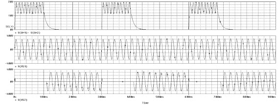
Relay voltages simulations:
Output voltage simulations:
Step 3: Make the Circuit
You will need a reasonable amount of money to create this circuit.
The construction of this circuit is NOT made to any standards and you will need to insulate the live wires underneath the box.
Conclusion
The circuit explained in this article has a few limitations. Not only the circuit has not short circuit protection but the relay can fail or even explode if the Rl1 resistor is very low. A possible solution is the connect a 12 V Zener diode across the relay (because I connected a typical and low cost 12 V DC relay) or use a more resilient relay that can handle high input voltage. This relay could be larger and possibly more expensive.
Another solution is to use a circuit breaker. A 2 Amp circuit breaker will provide short circuit protection.


Comments
Post a Comment